
www.auto-innovations.net
06
'26
Written on Modified on
High-Speed Electric Drive Axle Architecture for Passenger Vehicles
ZF engineers the High Revolution Drive to reduce electric motor volume and magnet mass through 30,000 rpm operation.
www.zf.com
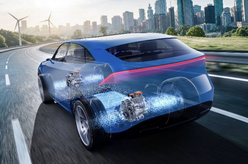
Automotive original equipment manufacturers face packaging constraints, curb weight limitations, and critical raw material supply risks when integrating electric traction drives into high-volume vehicle platforms. ZF Friedrichshafen AG addresses these electromechanical bottlenecks with the High Revolution Drive, a high-speed three-in-one electric drive system operating at rotor speeds up to 30,000 rpm.
Electromechanical Scaling and Torque Density Principles
Electric traction motor sizing is governed by electromagnetic torque, which scales proportionally with active rotor volume. Under basic mechanical power equations where power equals torque multiplied by rotational velocity, maintaining an equivalent electrical output while elevating rotational velocity reduces the required instantaneous electromagnetic torque. This mechanical dynamic allows engineers to downsize the active electromagnetic stack, cutting physical mass and total rotor cross-section.
The High Revolution Drive operates as an integrated three-in-one powertrain housing the electric motor, power electronics inverter, and mechanical reduction unit within a single structural enclosure. To convert high motor rotational velocity into tractive effort at the axle, ZF integrates a two-stage spur gear transmission featuring an approximate 18:1 reduction ratio. The baseline demonstration configuration generates 200 kW of peak mechanical power and delivers 3,500 Nm of peak torque at the wheels.
Acoustic Mitigation and High-Velocity Gear Meshing
Operating high-speed electric motors at 30,000 rpm introduces high dynamic stress on mechanical components, alongside severe noise, vibration, and harshness challenges. High rotational frequencies can excite structural resonances within the housing and amplify gear meshing whine across standard automotive operational bands.
Rather than attempting to damp acoustic emissions after subassembly, ZF applied integrated component engineering to align bearing stiffness, shaft deflection limits, and gear-tooth microgeometry directly with motor harmonics. Thomas Meiser, Head of the E-Mobility Business Unit at ZF, stated that component coordination was required to achieve durability and acoustic targets. The electric motor, gearing arrays, mechanical bearings, and tooth profiles were designed as a single unit to identify 30,000 rpm as the operational threshold balancing mechanical reliability and production cost.
Magnet Mass Reductions and Platform Modularity
Downsizing the active rotor envelope delivers significant material conservation across the electric machine. When measured against an 18,000 rpm baseline within the ZF SELECT driveline family, the High Revolution Drive reduces total physical installation space by nearly 25 percent and cuts overall mass by nearly 25 percent. Permanent magnet mass drops by 50 percent, lowering manufacturing exposure to rare-earth supply volatility. Despite the parasitic windage and churning losses characteristic of high-speed mechanical interfaces, total system efficiency reaches approximately 93 percent.
The powertrain functions as a derivative of the modular SELECT platform, accommodating passenger car outputs from 150 kW to 200 kW on both 400-volt and 800-volt electrical architectures. Automakers can integrate the system into emerging electric vehicle architectures without custom structural retooling. ZF is in technical discussions with multiple vehicle manufacturers, with series production targeted for 2030.
Additional Context:
This section details technical specifications and competitive benchmarking not included in the original product announcement.
Mainstream automotive electric drives commonly operate at maximum rotational speeds between 12,000 rpm and 18,000 rpm, paired with single-stage or low-ratio two-stage planetary and countershaft gearboxes providing reduction ratios between 8:1 and 12:1. Advanced series-production high-speed benchmark drives, such as high-output permanent magnet motors found in contemporary performance platforms, typically top out between 20,000 rpm and 22,000 rpm to avoid rotor sleeve delamination and excessive centrifugal mechanical strain. Operating at 30,000 rpm requires specialized rotor retention methods, such as carbon-fiber overwrapping or high-strength alloy sleeves, alongside high-frequency silicon carbide (SiC) power semiconductor switching within the inverter to supply the high fundamental electrical frequencies demanded by high pole-pair rotor geometries without inducing thermal saturation.
Edited by Natania Lyngdoh, Induportals editor, with AI assistance.
www.zf.com
